Clinton's Wooden
Cylindrical Flute
Introduction
We're looking here at John Clinton's cylindrical wooden
flutes to see what similarities and differences there are when compared to
his conical systems and his metal cylindrical flutes.
Our examples
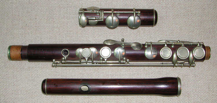
We have two examples, subtly different. The first is
no 5009, from the Helen Valenza Collection:

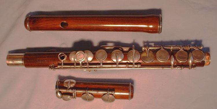
The second, No 5055, is in the possession of English collector,
Andrew Kirby:

The most immediately obvious difference is the colour of
the timber, the lower flute is in unstained cocuswood, the former is also
cocus but has been stained.
Perhaps the next most obvious difference is that on the
lower instrument, the G# key cup is in line with the other key cups,
rather than being at the end of the L4 key on the side of the instrument.
It's still operated by L4, but through a linkage rather than directly.
It's also operated by L3; the arrangement and reason for this will be
shown below.
The top tenon on the body of the lower flute is unusual
too, in not having the tenon cork seen on the upper flute. It's
possible that this is due to a repair. The tenon cork isn't really
needed here, as there is a telescoping tuning slide built into the inside
of the tenon and socket.
Characteristic features

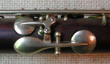
This flute shares a characteristic feature with many other
of Clinton's flutes - the single thumb lever which can play either C or
Bb, depending on whether the top keys are being fingered B or A. The
characteristic is common, but the method of achieving it varies.
In this model, the logic is performed by a side mounted
C-key, driven by the thumb key and by the tail of the B key (see schematic
below).
Unusual features (images)
Perhaps the most unusual feature of these flutes is the
size of those key-plates, and presumably the holes under them. And
the fact that they taper from small near the top of the flute to
absolutely enormous at the foot. These are in fact the "graduated holes"
of Clinton's 1862 Patent.
Keywork
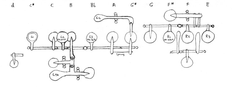
To find out how the thing really works, we turn to a
schematic drawing of the mechanism, shown below. The note names at
the top of the drawing tell us which note will be played when a key cup
directly under that name is the first to be opened. The home
positions of the fingers are shown as L1 to 4 and R1 to 3 (R4 being used
on the foot keys). Note that there is no hole under L2, L3 and R1 -
they are just touches. All the other key-cups have pads and holes
under them.
Note that the schematic relates directly to the lower
instrument pictured above. The upper instrument has the G# key-cup
directly on the other end of the L4 lever. On that instrument, L3
closes only the A hole, there being no linkage to the G# cup. The
benefit of the arrangement shown is that full venting is maintained for
all fingerings (ie every hole below the first one opened is kept opened).

Interdependencies
-
L1 closes c (and of course c#)
-
L2 closes c, B and the duplicate c (if it has been
opened by the thumb lever)
-
L3 closes A (and G# if the automatic G# mechanism is
fitted)
-
L4 opens G#
-
L Thumb opens duplicate C (unless held closed by L2) and
Bb
-
R1 closes G
-
R2 closes F#
-
R3 closes F#
-
R4 operates the foot keys (not shown).
-
R2 can also open the d trill key (touch between R1 and
R2)
-
R3 can also open Short F (touch between R2 and R3).
Bore
Unfortunately, I do not have bore information for either
instrument, other than to note that the body bore is around 19mm. We
can be pretty confident that it adheres closely to that of Boehm's 1847
cylindrical instrument. Many, perhaps most makers in the second half
19th century made flutes - either simple-system, multi-keyed or both -
based on Boehm's bore, most stickling very closely to the original
dimensions. Indeed, only those that deviated significantly from
Boehm's pattern seemed to get into trouble. Boehm had done his
homework well.
Given that assumption, we can guess that the head bore at
the stopper starts around 17mm, and expands to 19mm more or less linearly
over the next 130mm, remaining at that diameter for the rest of the bore.
Venting (chart)
Playing qualities
Pitch (graph)
Tuning (graph)
Fingering (chart)
Links (similar and different flutes)
As you can see, lots of work to be done yet!
|


