Introduction
It wasn't long after starting
to play concertina that I started wondering about how these things work,
what sorts of pressures and flows are involved, etc. And it wasn't
very long after starting to do some experiments to find out that I
realised the need for some basic measuring devices, set up in some
convenient arrangement. I needed a "Concertina Pneumatics
Laboratory". Surprisingly, Ebay didn't seem to offer such a thing,
so I decided to build my own.
Of course one quickly runs
into the old paradox that faces all researchers - you don't know how
best to approach the task until you've completed it, and I have no
reason to hope for better luck. The only precaution I could take
was flexibility. Only time will tell if I was flexible enough.
"Cheap" and "Dirty" were my
other watchwords. I'm not being paid for this; indeed it's taking
away time I should probably be spending on more profitable endeavours,
like making flutes or fixing carillons. Further, as fancy
construction and fine materials are not going to add anything to the
quality of research, it's out the window with them. So, if you are
prepared mentally for an abomination, we can risk uncovering it to your
naked gaze....
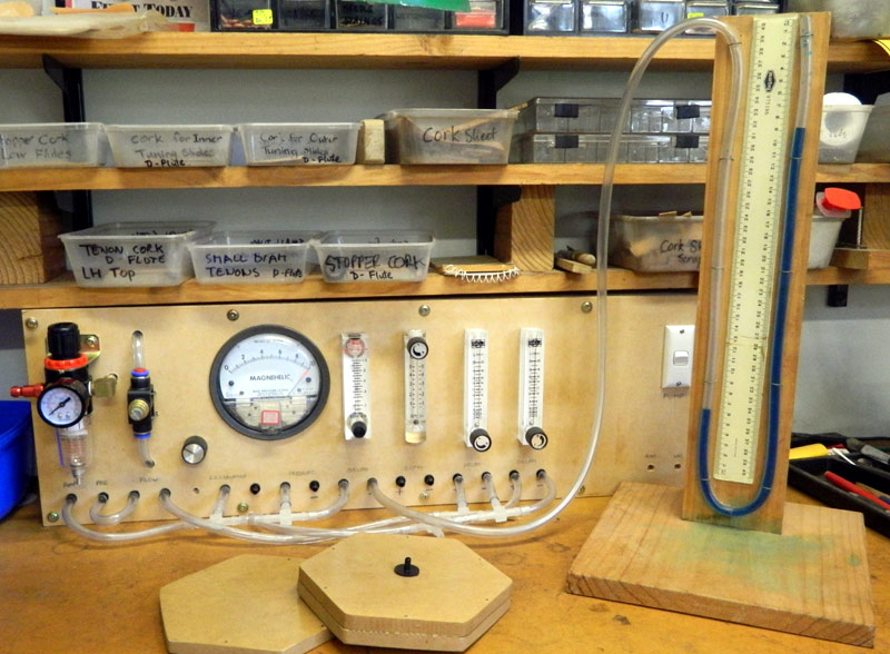
There it is, in all its
primitive splendour. I'll walk you through what it comprises....
Pressure Regulator
On the left we see a typical
air pressure regulator. It takes air from the workshop compressed
air line and reduces it down to safer pressures. We'll be using it
just off the bottom of its range. This isn't Mythbusters - we're
not looking to blow up concertinas here!
Ball Valve
Not shown, because it hadn't
shown up in time, is a ball valve to disconnect the whole system from
the compressed air line. It will go between the regulator and the
bright-red quick-release connector protruding from the regulator.
Flow Regulator
Next we come to an air-flow
regulator - essentially a needle valve. I figure it will be handy
to be able to keep a control over maximum airflow rate of which the
system is capable.
Low Pressure Regulator
The knob to its right is a
low pressure regulator, working in the 0-1.5psi (about 1000mm water
column) range. It's ratted from my "Magnehelic Flute Leakage
detector".
Pressure Gauge
The big round dial is a
Magnehelic Differential Pressure Gauge, 0 - 10" water column, also part
of the original Flute Leakage detector. As we'll be favouring
metric measurements, we'll regard it as 0-250mm of water.
Flow meters
Then we come to the first of
4 air-flow meters. Well, not just meters, but combined meters and
controllers. The knob (at top or bottom of each) operates a needle
valve, which can be used to set flow very finely. Or backed right
out so it doesn't influence the airflow in the system to which it is
connected.
The meter itself consists of
a tapered bore in a block of acetate. A bead lives in this bore
and is blown upwards by the air flow through the bore. The heavier
the bead and the steeper the taper, the more airflow is needed to push
the bead up the scale. Wonderfully "first principles".
Why four? To cover the
range of air flows we can expect to encounter. The four flow
meters are:
-
The 1 SCFH (Standard
Cubic Foot per Hour) measure that came with the Magnehelic Flute
Leakage detector. We'll regard it as a 0.5LPM (Litres per
Minute) meter. I found it generally too sensitive for
concertina work, other than measuring leakage through one pad at a
time.
-
A 5 LPM meter from China, ten
times less sensitive than the first one.
-
A 20 LPM meter also from
China, four times less sensitive again, and
-
Another one of the same, to give
us up to a total 45.5LPM capacity if we need it. That's a winecask
full of air every 6 seconds!
Electric pump
At the extreme right, lurking behind
its white on-switch, is the aquarium pump that powered the Flute Leakage
Detector. It's rather underpowered for concertina research purposes, but I
want to be able to reconstitute the original arrangement for flute testing.
U-tube Manometer
Not built into the pneumatics lab box
because of its size is your good old school laboratory manometer - essentially a
U-tube half filled with water. Another wonderfully "first-principles"
tool. Some blue food colouring makes the water easier to see, and an
in-built rule makes it easier to note readings. You can also see that if
you even momentarily overload it, the blue water makes a bit of a mess on the
base of the instrument!
The Magnehelic pressure gauge is more
convenient than the manometer, but if you want to measure pressures in several
parts of a system at the same time, manometers are cheap and easy to build.
Digital Manometer
Not shown in the image above is a digital manometer,
again from China. Neat little hand-held unit, it can measure up to
1400mm of water (10psi), and read out in any of 11 units of pressure.
Connecting it up with the other two pressure gauges, they all agree to
within 2%, plenty good enough for our purposes. Reassuring.
And inside?
You might think that the most intriguing part is yet to come -
how is it all connected up inside? You'd be disappointed - there is
absolutely no interconnections inside. All of the items are brought out to
that row of tubing connectors along the bottom of the panel. The aim of
the lab is to give us flexibility - different setups can be constructed at will
and within minutes using scraps of poly tubing, T-junctions and anything else we
find necessary. And I can quickly reconstitute the flute leakage detector
when work calls. Room to move
You'll notice some blank panel space to the right of the flow
meters. Room to add more devices if necessary. We really don't know
where this is leading! Real-world adapters
And included in the image, in front of the lab, is an adapter to
connect to the end of a concertina. It's a reminder that we are going to
need all sorts of adapters and jigs to be able to measure the various parameters
we expressed interest in at
Concertina Issues to be investigated. But no rush and no problem.
We have a well-equipped workshop in which to make those devices, and we can add
them as needs dictate.
And it works!
You've probably noticed that the blue water is not at rest, but
in fact is indicating a pressure of 254mm of water (the difference in height
between the two columns). The Magnehelic pressure gauge is agreeing,
calling it 10". The air supply is the internal aquarium pump (via the
white switch - down is ON in Australia), regulated by the low pressure knob.
I've also tested the compressed air line system, and can confirm that we can
supply 40 or more LPM under controlled conditions to the hapless test subject.
Well, it almost works!
If you look very very closely at the flowmeter directly to the
right of the pressure gauge, you might notice something distinctly odd.
The tiny bead is sitting just above the 0.2LPM mark. But where is this
cupful of air per minute going? The output of the flow meter is going to
the manometer, and the manometer water level is stable. It sure ain't
getting out that way. I quickly eliminated all the obvious
solutions, eg, a tube connection is leaking. So we're looking for
something not quite so straightforward. Demonic infestation, for example.
Then a small light began to glow in the back of the mind. Could this be an
"Alternating Current", rather than a "Direct Current" problem? An aquarium
pump doesn't provide a constant flow of air, but a continuous series of pulses,
as the vibrating reed inside operates a simple pump. Who knows what a
floating-bead type flow-meter thinks of that? And its response is likely
to be dependant on the nature of whatever is connected. Not Good!
And this is not just an inelegance. If we assume that the pump waveform is
similar to a half wave rectified mains signal, the crest factor is 2:1.
That means that the peak pressure would be twice the average pressure. Our
manometer or the Magnehelic pressure meter might be measuring 250mm of water,
but the peaks could be reaching double that. The inertia of the air in the
lines will tend to even out the peaks but even so, we might be compromising our
measurement accuracy by testing say pad leakage at pressures the pads and
springs were never intended to have to deal with. And we know
it's real - I was able to prove the pulsing nature of the pump simply by putting
the end of the tube from the pump into my mouth. Drrrrrrrrrrrrrrrrr it
vibrated, as my cheeks slowly filled. Surely, we need something to iron
out those pulses into a (relatively) constant flow. We need the pneumatic
analogue of the electrical "reservoir capacitor" you find in every power supply
circuit. A plenum. ("Plenum" is Latin for "full", and is the
opposite of "vacuum".)
Easily made, about 350mm length of 50mm diameter poly water
pipe, capped off at both ends, with the joints taped over, just for luck.
A simple tube connector on each end. Popped into the (previously) empty
box and cut into the pump line. Back round to the front, turn it on,
problem solved! Pop the tube in your mouth, and your cheeks inflate
smoothly without the vibrating effect. Lovely. I think we're there.
Conclusion
Hmmm, now we have no excuses. We're going to have to do
something!
|