Introduction
Rudall & Rose brought out
their Patent Head in 1832, making it the
subject of their first patent.
They seem to have made quite a few of them, and because of their unusual
features they often show up requiring maintenance. The purpose of
this page is to provide a place where information, hints and tips on this topic can
be assembled.
Stop!
If you are unfamiliar with
the Patent Head, proceed with caution. You cannot manually alter
the setting of the tuning slide as you would with normal flutes -
attempting to do so will damage the internal mechanism. Attempting
to turn the head relative to the barrel will snap off the guide key
shown at top left in the image below.
Only ever adjust the tuning
slide position by rotating the end cap and proceed cautiously. As will
be seen below, the screw mechanism can be easily damaged by excessive
force on the cap, and replacing the damaged items will involve a lot of
painstaking work.
Review the drawings and
photographs on the pages linked above before proceeding.
Partial disassembly
As shown here, full
disassembly is quite a business, but is fortunately not necessary for
most maintenance tasks.
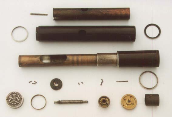
(Click here for an item-by-item explanation of the
parts above)
For most routine maintenance, it is enough to separate the
barrel and head sections.
To separate the barrel section and inner sleeve from
the head section:
-
Gently unwind the end cap (turning counter-clockwise) until you reach the end of slide travel (the slide
opening should be about 30mm, about 1.25").
-
Do not use force to go any further! Indeed, turn
the cap slightly inward to free the stopper from the end stop.
-
Use a suitably prepared rod inserted up the bore to
engage the face of the stopper and rotate it counter clockwise until it
can be heard or felt to "click" on the end of its thread.
(Suitable rod suggestions below.)
-
Undo the cap further until the head comes right off.
-
Use a thin rod (eg a standard metal flute cleaning rod or
some stout wire)
through the hole in the cap end of the inner tube to push the stopper out
through the barrel socket. Be careful not to damage the threaded hole
in the centre of the stopper. Indeed, it might be wise to drop
in anything suitable that will fit through the embouchure slot on the liner
(eg a small washer or coin) to spread
the load of pushing out the stopper.
Suggestions for the rod above:
-
In principle, the rod:
-
should be of the largest diameter available that will
freely pass up the bore. In practical terms, that probably means
16mm (5/8") as material in these dimensions is readily available. A thin rod should not be used, as it will apply
its pressure to the unsupported middle of the stopper face
-
should be finished off squarely at the stopper end, and
rounded comfortably at the handle end,
-
should stick out long enough to be able to put some
rotational force on it, and
-
should have something of a high friction surface treatment at
the stopper manipulating end.
-
I have used my usual stopper removal rod, a length of 16mm diameter delrin. To improve the gripping ability, I dropped a rubber bung down the
head bore first. The bung should be a free fit and be inserted so that its
wider end abuts the stopper face.
-
Jem Hammond reports success with a thick wooden dowel with a hollowed
end
-
David Shorey reports success with a piece of closed cell foam
punched out and glued to the end of a dowel.
Having subsequently tried David's suggestion, I'm going
with that from now on!
At the rod's other end, it could usefully have grooves
to mark:
-
the stopper distance when the slide is fully
extended, about 16mm
-
what we find our stopper distance to
be at A440 (to be determined), and
-
the stopper distance when the slide is fully closed,
about 21mm
Elsewhere on the rod, somewhere where they won't be
confused with stopper marks,
These would make it possible for the owner / repairer to
check the operation of the mechanism easily.
Further disassembly
For most routine maintenance purposes, further
disassembly should not be needed, but these notes are included in case
you need to go further.
To remove the two-speed shaft:
(Why would you want to do this? I've found it
useful to do when replacing the cork sheet around the stopper.
As we'll see below, the amount of friction is critical, and it's useful to be
able to screw the stopper onto the end of the two-speed drive shaft to
be able to offer it (facing the wrong way!) into the copper tube at the
barrel end to test the fit.)
-
unscrew the two small screws to remove the end cap.
Immediately put the tiny screws into a ziplock bag or screw them
back into the drive plate below the cap for safety!
-
remove the pin that secures the plate by
rotating the end of a flat screwdriver in the gap between the tip of
the pin and the rim of the plate. Pull the loosened pin with
long-nose pliers. Add these bits to the zip-lock bag!
-
remove the now-loose drive flange and push the
exposed end of the two-speed drive shaft to eject it into the head.
Going further:
The two-speed drive shaft
Interesting to note that the four-start thread of the drive
shaft (labelled "a" in the drawing below) at least on the examples I have seen,
is not so uniformly threaded that it will run freely in all four possible
starts. When reassembling, make sure to test all four options and pick the
most free-running start!

The course thread fits a 13TPI thread gauge convincingly, but,
given that there are 4 separate threads, this really implies a threading rate of
3.25 TPI. It's outside diameter is 7.24mm, somewhere between 9/32" (7.14)
and 5/16" (7.9mm).
The finer single-start thread at the stopper end of the drive
shaft has a diameter of 4.92mm, slightly larger than 3/16" (4.75"). The
thread, which also takes the Acme form, is 20tpi, which makes it still coarse by
normal standards. The nearest equivalent screw in BSW, 3/16", has 24tpi.
The drawing in the patent document shows the stopper with a
sturdy central boss to provide plenty of depth for the screw thread. The
example before me just has a 1.67mm (nominally 1/16"?) brass plate at that
point. At a thread pitch of 1/20", that only allows a thread depth of 1.25
turns!
Given the unusual nature of the threads, great care should be
taken of the shaft and the stopper thread, as replacing them will require some
pretty nifty thread cutting on the machine lathe.
The Stopper Face
It seems common that the stopper face on this head is missing,
suggesting that it was inadequately held in place. We understand it to be
of sterling silver, approximately 0.4mm thick, and of diameter just able to move
freely inside the bore. The bore measures at about 18.67mm in diameter on
the sample under examination.
It has been suggested that the stopper face is held on using
soft solder, but this has not been confirmed. The cylindrical part of the
stopper is made from brass sheet soft-soldered along the seam, and the tapped
plate inside is also soft soldered in place. Given the very good
likelihood of these other joints coming unstuck while reaffixing the face, it
might be cheap insurance to glue the face on instead of soldering. This
might also save replacing the stopper cork if it is still serviceable.
Here's a solution that works. Clean the inside of the deeper end of the stopper tube and score
it to provide keying for the glue. Score the back of the face plate
similarly. Coated the inside of the deep end with epoxy, being careful to
avoid any getting near the central tapped hole. Place the face plate with
the scored side upwards on the desk, and position the stopper centrally on top
of it. The glue should run down inside and form a more-than-adequate bond.
A design weakness?
Something that has always puzzled me
is what keeps the stopper from rotating? If it rotates it will mess up the
desired relationship between stopper distance and slide opening. The only
answer I can come up with is that it is the friction between stopper and the
tube it runs in. So we don't want that to be too little. But, for
free movement of the slide, we can't afford that friction to be too high.
I never like systems that depend on the Goldilocks perception of ideal friction
- "just right"!
But thinking about it some
more, there is a "sort of" anti-rotational force at work. The
silver end of the stopper runs through that section of the inner tube
that has the long embouchure access slot in it. So we can imagine
that the cork facing "gets used to" having a bit more freedom in that
sector, and will thus be loath to leave it. Hmmmm......
Reinstalling the stopper
The need to get the stopper
in the right part of its rotation means we can't just
screw the stopper onto the end of the two-speed shaft and forget about
it. If we do it
up too tight, then it will definitely rotate, and get us into all sorts
of trouble! If we don't put it on by enough turns, it will
unscrew. Unfortunately, it seems Rudall & Rose have left us no
real guidance in terms of installing the stopper, so I guess we have to
come up with our own. Here's my guess (but don't do it yet until
you consider the next section):
-
screw the two-speed shaft
into the end of the inner liner as far as it will go. Make
sure to use one of the "starts" that spins freely, not one that
binds.
-
drop the stopper into the
barrel end of the head, with the silver surface last to go in
-
use your stopper rod with
the prepared soft face to push the stopper up to contact the end of
the two-speed shaft.
-
Holding the end of the
two-speed shaft to prevent it rotating, use your stopper rod to wind
the stopper onto the end of the shaft. Stop when it starts to
rotate the two-speed shaft.
-
Now, back the stopper off
by turning your prepared rod counter-clockwise. How much to
back it off? Aha, that's the $64,000 question! Certainly
"enough to ensure it doesn't jam on and rotate"! And certainly
"not so much as it will unscrew partway through the travel.
Ask Goldilocks, I guess.
-
If you happen to know
what stopper distance you'd like when the slide is closed,
here's your opportunity to set it. Hold your outer head
against the inner head, with the two rings at the bottom of the head
touching. Now use a rule to measure from the centre of the
embouchure on the outer head to the face of the stopper on the inner
head. On the example in front of my, and with the stopper just
backed off about 1/3rd of a turn, I'm getting around 20mm. You
could make it less if you want by undoing the stopper more, but not
much less!
-
Now, once you have the
stopper installed to your satisfaction, why not put a mark on its
face showing which direction the embouchure hole is. Then a
glance down the bore or even through the embouchure hole will be
enough to alert you to the stopper having rotated. (So far,
I've only dared to use a marker pen for this, but ideally something
that won't rub off would be better.)
But wait! To
lubricate or not?
There's a general rule that
any metal-to-metal contact requires the presence of a lubricant to
prevent "metal fretting". So I think the two-speed shaft
definitely needs a good smear of lubricant.
Given what I said above about
the right amount of friction, I wondered if I should not grease the
stopper cork. But then I thought a bit of stickiness (stiction?)
might actually help, so I did that too.
And finally, we definitely
need the inner tube to slide smoothly inside the head, so I gave that a
good smear too. I figure also that if there is leakage between any
of the sliding parts, some goup will help stop it.
But there is one place we
definitely don't want to lubricate, and that is the face of the stopper.
For two reasons. One, we depend on grabbing and rotating it by
friction with our stopper tool. Secondly, lubrication will prompt
beading of the moisture from our breath, and we don't want to encourage
that. So keep the stopper face dry.
Probably anything that won't
go rancid with time will do as a lubricant. I used vaseline.
Final assembly
Assuming you're happy with
all the above, go ahead, lubricate the bits and assemble. Once you
get the stopper attached with the desired degree of backing off, slide
the outer head over the copper tube, and let the brass end of the
two-speed screw pop through the head's end flange. Pop on the
driving flange and secure it with its pin. The pin seems to work
better from one side than the other.
At this point, it's wise to
check the operation of the system a few times by winding from one end to
the other, and testing the stopper distance each time. If it's
changing, the stopper is rotating! On the one in front of me, I'm
getting a slide range of about 30mm, with a stopper distance of 16mm
with slide open and 21.5 with slide closed.
Now if that all seems
satisfactory, carefully clean a space to work in, retrieve the cap and
the two very tiny screws from their ziplock bag, and secure the cap to
the driving flange. Wise to do this in a tray so if you drop the
screws they will be findable!
Some closing thoughts.
-
If I owned a Rudall &
Rose Patent Head (and I do), I would want a patented rubber-ended
stopper tweaking stick to be able to carry out the operations above.
(And I have made one!)
-
We know that at least
several pitches were popular in England at the time. Older
pianos would be tuned to A 430, while the young bucks at the
Philharmonic were raging up around A452-455. Voices of reason
(see Society of Arts Pitch)
were calling for compromise of A440Hz, but that didn't happen until
close to the end of the century. It may be the case that the stopper
distance for A440 that we need today might not be optimised.
With the patented rubber-ended stick, the owner might be able to
fine-tune the stopper position a little to make it better. But
note - this might mean the slide is not capable of movement
throughout its full range, either because it jams at one extension
or because it suddenly comes loose at the other. Up to the
owner to decide on the merits I think!
|